The 300 inch challenge layout is going to exploit DCC as much as possible, so electrifying the turnouts is an important job. I’m using SEEP point motors, though I was tempted to experiment for the first time with something more sophisticated. SEEP produce 3 slight variations of point motor:
- PM1 – Non Latching with built in switch
- PM2 – Non Latching without switch
- PM4 – Latching with switch
As I’m using PECO turnouts which have springs to hold the point blades in place I don’t need the latching model, but as I’ve modified the point for DCC I will need to use the built in switch to change the polarity of the turnout frog, so I’m using the PM1 design. Connection to DCC will require an accessory decoder, and I’m opting for my usual choice – a Lenz LS 150. the LS150 has no problem in giving sufficient output to fire the solenoids in the SEEP PM1.
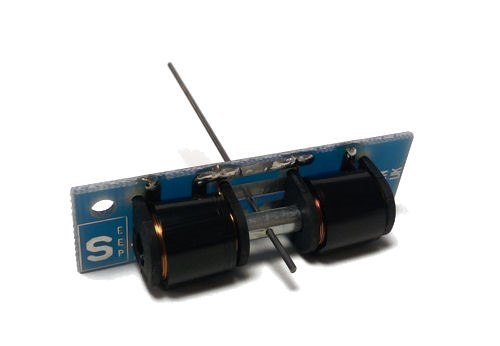
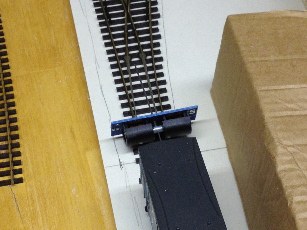
Fitting the SEEP PM1 is quite straightforward, the trick is getting the switch properly lined up. To do this I make sure the PM1 is set so that the pin that attaches to the turnout is set in the centre before putting the motor in place. The photograph below shows the use of a small piece of plastic with a groove cut into it to hold the pin in the right place. Annoyingly, at some point SEEP have changed the design slightly, and I ended up with a motor of both old and new design. The different gaps between the solenoid coils requires two completely different wedges!

Seep point motors ready to fit with switch held centrally
The turnout blades need to be central too, and this is a little tricky as the internal spring in the PECO turnout isn’t very happy when it isn’t switched one way or the other. My crude answer to this is to wedge something between each blade and the outer rail of the turnout. Two small brass screws were very effective for this.

Using screws to centralise point blades
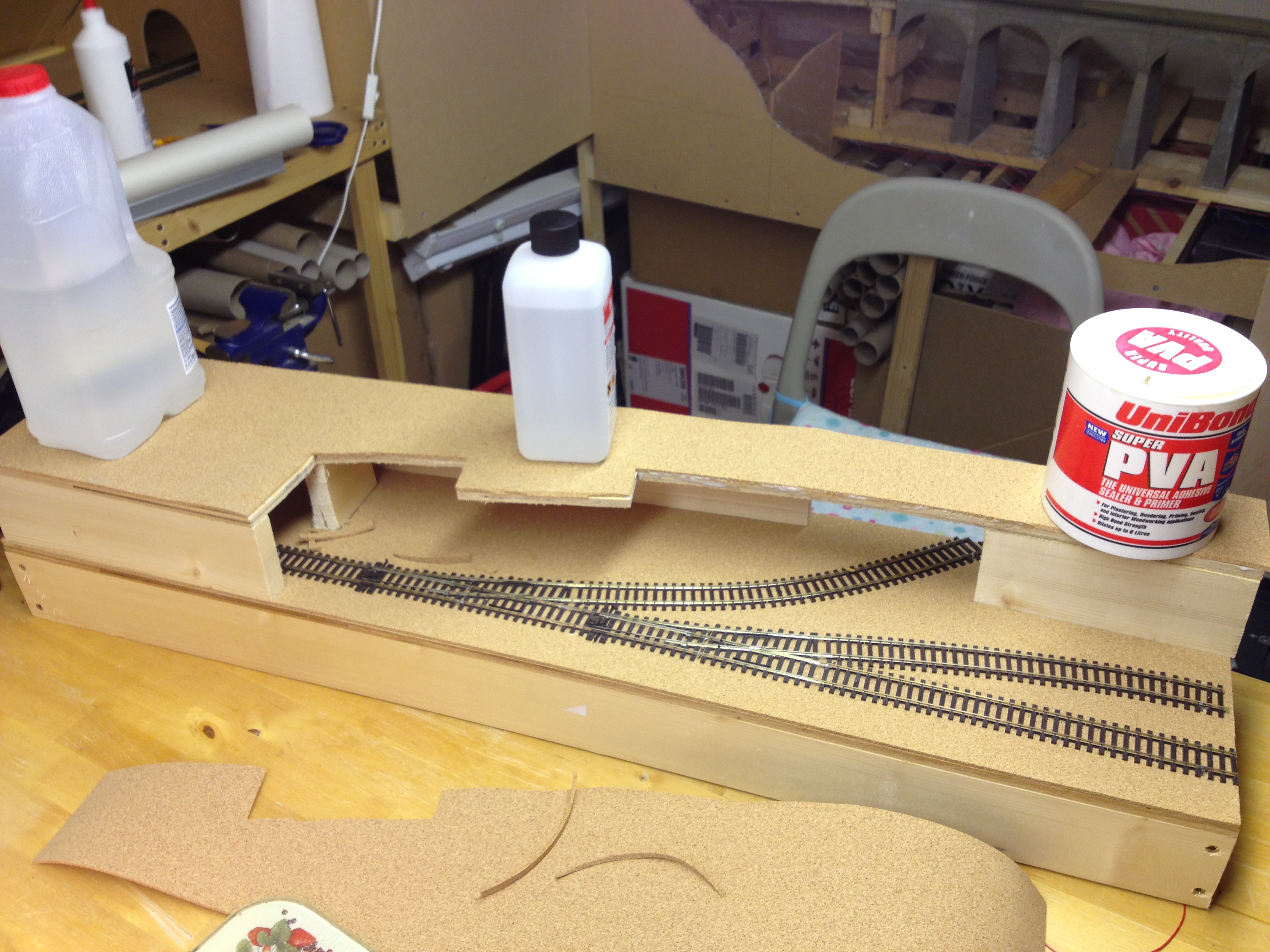
with everything held centrally the point motors can be fitted to the underside of the board. Make sure the point motor is square to the turnout, otherwise it wont fire smoothly.
The picture below shows both motors in place along with the LS150 and the feed to the turnout frog ready to be attached to the polarity switch in the SEEP PM1

SEEP point motors fixed in place
Wiring the SEEP PM1 is quite straightforward. The solenoid is connected to a set of outputs on the LS150 and the switch to the DCC power bus and the point frog. The attached PDF provides more information.
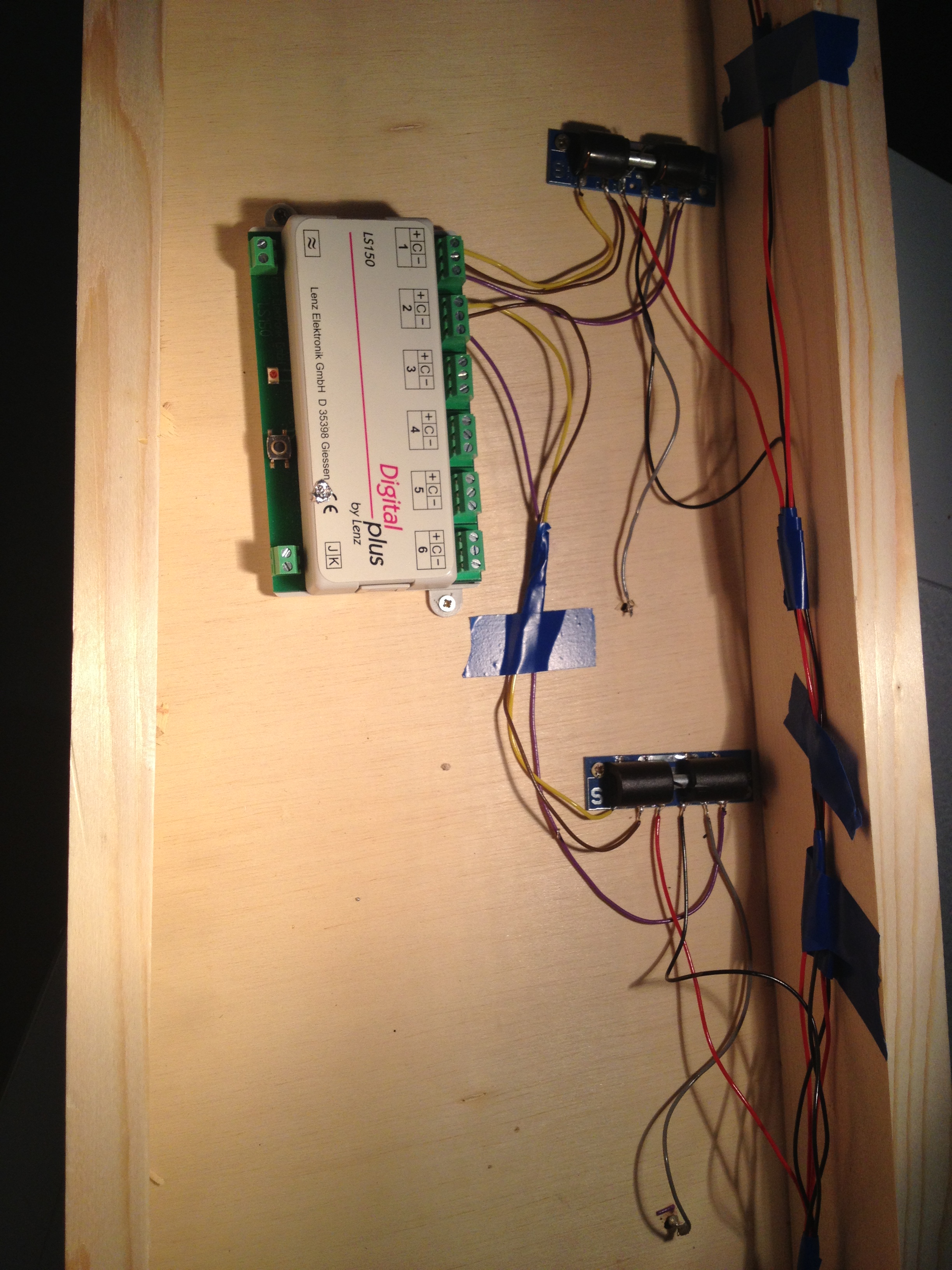
SEEP point motors connected to Lenz LS150
The Lenz LS150 has 6 outputs, and only two will be used for turnouts on the 300 inch challenge. The four spare outputs will leave me with plenty scope to experiment with uncoupling devices. I’d really like to make the shunting puzzle part of the layout operate hands free.


