Time to DCC fit the austerity, as promised. A change of plan though, the OPTI chip is too big to fit so I’ve opted for a smaller ZTC255 that was spare in my toolbox. I dare say the mini version of the OPTI would be fine.
1) Unclip handrails from cab sides: These are attached to both body and chassis and might bend horribly if you dont detach them.
2) Remove front pony truck: One screw will release this, the spring can stay in place as it will move to one side to reveal the foreward fixing screw beneath
3) Unclip brake cylinder from under cab; This has to come off to get at the rear fixing screw, but it clips off quite easily.
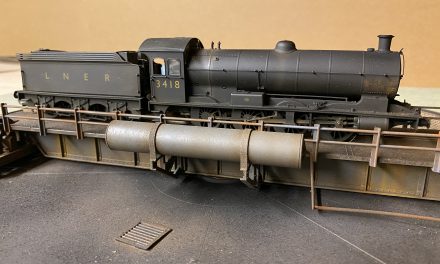
4) Remove 3 body fixing screws: Be careful to undo the right ones, the others secure the plate that retains the wheels in the chassis block, and if you take this off wheels coupling rods and valve gear can easily fall apart.

This photo shows the position of the screws that need to be undone
5) Gently remove body from chassis, this reveals the motor assembly, take care to note the tight fit within the body and the complete lack of any space around it to take a decoder. The only option is to create space by removing the printed circuit board and the plastic plate it is mounted on and placing the decoder in its place.
")
6) unscrew pcb from above the motor; The screws are tiny, you will need your smallest phillips screwdriver.
")
The PCB removed showing plastic mounting plate below. This also needs to be removed
7) unsolder wires from pcb and discard the pcb, also remove the plastic mounting plate the pcb was screwed onto, otherwise the gap between the top of the motor and the underside of the smokebox wont be big enough to accomodate the thickness of the chip. The circuit board has no purpose in DCC; in DC it would provide TV and radio interferenc supression, in DCC the decoder does this anyway.
8) unsolder wires from the motor and replace with wires from the decoder (grey replaces black, orange replaces red), having first shortened the decoder wires, there isnt much room so the less spare wire the better. Its wise to shorten the unused decoder cables as much as possible, they will only get in the way later, and there really isnt agoing to be any space for anything that doesnt need to be there.
9) Connect the decoder to the wires from the pickups: join black and red from decoder to black and red connecting to the wheels, if you use heatshrink remember to put this on first.Remember the saying “red and black to the track, orange and grey the other way”
10) Fix the decoder in place: I taped the decoder to the top of the motor, having first covered the metal case of the motor with insulating tape to prevent any accidental connection to the decoder. The ZTC255 has a plastic wrap around it in any event, but I like to be doubly sure. Tape the wires going to the wheels against the backplate of the motor to make sure they are out of the way when the body goes back.
11) test to see if it works. No point intidying up the cables or putting the body back until you know it powers up. Put it on the track and address it (0003 by default) with a controller (I use the throttle facility in decoderpro and run it back and forth on the portable programming track powered through the Sprog programmer. The sprwill happily deliver sufficient current to drive a single locomotive.
")
Insulation in place and ready for reassembly
12) insulate the cables where they were soldered together, either with tape or by shrinking the heatshrink, and tape the cables neatly to the back of the motor to make sure they are out of the way when the body refits. The gap is extremely tight, and it easy to trap a cable.
13) replace the body carefully, make sure the cab handrails line up to their original holes, if not, you possibly have a cable trapped between body and chassis. Its a real fiddle to avoid this, I needed 3 attempts.
I’ll demonstrate how I programmed the decoder using my portable programming track, Sprog, and DecoderPro3 in the next blog entry……


Trackbacks/Pingbacks