There is a great DCC myth that you need to modify all your turnouts to work with DCC. This really isn’t true, and my Rede Valley layout has been operational for some time using PECO turnouts straight out of the box, mainly because most of the track was already laid before I converted to DCC.
Over time however there have been some problems. The main one is relying on the point blades to provide power to the frog. Over time the springs have become less effective at fixing the blade to the adjoining rail and frequent stalling takes place until I address the issue with a pair of pliers to tighten the clip that retains the spring. This might be to do with the Rede Valley being in the loft and subject to extremes of temperature. This issue would be just as much a problem on a DC layout.
The classic reason for converting a turnout for DCC is to prevent short circuits as wheel sets that are out of tolerance simultaneously touch both turnout blade and adjoining rail of opposite polarity as they cross the turnout. Personally I’ve never really had a problem with this, except with one loco on one particular turnout, and I’ve cured the problem without altering the turnout. The secret is making sure there is good track alignment leading into the turnout and avoiding sharp curves straight out of the heel of the turnout that will angle the locomotive as it reaches the critical spot over the blades.
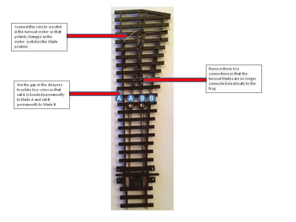
My micro layout only has two turnouts, and I decided that this was the ideal test bed for doing things “properly”. I’ve chosen electrofrog points over insulfrog deliberately as I don’t want small wheelbase engines stalling on the frogs when shunting at low speed. So for those of you that are interested here’s how to convert a Peco Electrofrog turnout to full DCC specification.
When I lay the turnout I’m going to use an isolating rail joiner on each of the two rails leading away from the frog, as otherwise both these rails would be live with the same polarity, and any engines parked on the line that the turnout is switched against would then cause a short in DCC.
There is a further modification that can be carried out to avoid this, and it involves cutting a gap in each rail close to the frog to isolate the rails leading out of the turnout from the frog and soldering wires to the isolated rails and the outside rails of the turnout so that they are connected permanently to the correct DCC polarity.
I haven’t incorporated this final mod on the micro layout as I’m putting a separate power feed to each of the roads beyond the turnout.